
TE
@Terry Cockerell
Hello Terry. This actual topic was discussed on this forum about a year or two back. I believe if you did a search you may find it. I don't think it mattered what wire got the power but I do think you need to get better advice than what I have posted.My clock has never had any power applied to it so I can't show a picture of it. I will be watching this for proof of how to wire a seemly simple clock. I certainly share your caution.
 
 
Gary Parsons
Hi Gary, the clock is mounted in the dash board and I have connected most of the other wiring up. It is difficult to see the top of the clock but I can clearly see BATT at the side of the LHS terminal.
One of the other Postings that I found stated the terminals on the clock say BATT and GRD.
I will have a closer look today with a small mirror. I would expect that BATT connects with the negative ammeter terminal and the GRD connects with a convenient body earth.
I was on the verge of removing the clock to check it but think we have found the solution.
I will let you know later today.
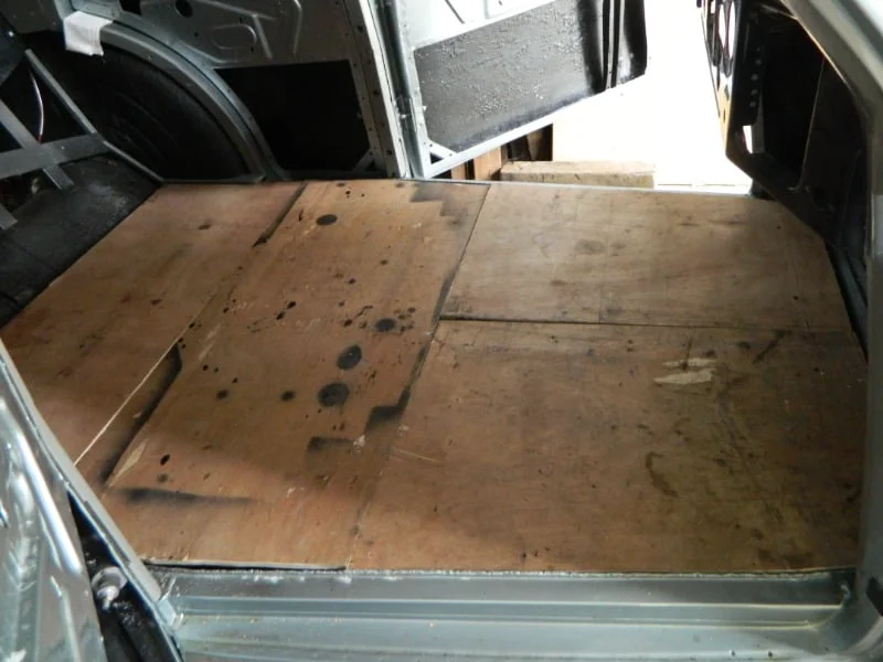
Gary using a small mirror and torch I was able to see that the RHS terminal says GRDThe LHS terminal says BATT consequently the BATT terminal must connect with the negative terminal on the ammeter.This was looking at the back of the clock.To make working on the interior easier I had made a set of temporary floor panels using plywood.My motor trimmer/upholsterer was most impressed as it was so much easier on his knees while installing the head lining.You just need a couple of pillows to put your head on while doing the dash wiring.
Terry it sounds like you figured it out but... If you might need a picture of the back of the clock I can help. My dash panel is on my work desk and any picture of the back of it can be easily done. I probably have already posted pics of every dash gauge on this forum when I was restoring my dash.
I really like your idea about protecting your knees. Thats a great idea.
What is the black stuff on the floors and inside the doors? I suspect I know but would like to hear what you applied. I don't recall if the floors had undercoat but I know the inner back fender area sure does. I have something original inside my doors and on the roof panels. It appears to be a treated material like cardboard. Pictures on request.
 
 
Gary Parsons
Gary the black stuff is Septone body deadner or a bitumen type body paint. As well as restore the car I am doing my best to preserve it well into the future. The doors and roof originally had a cardboard type material impregnated with bitumen put on the insides to help deaden the sound. This all had to removed for sandblasting etc. Some doors had new skins fitted.
I have layered the body deadner in the bottoms of the doors to direct any water to the drain holes.
The underside of the complete body including fenders have been given the same treatment.
It is going to be a driver and a good one.
Hi Terry,
 
I was trying to help you taking a photo under the dash, but this only helped me finding out why my clock isn┬┤t working... no cable is connected :whistle:
 
but perhaps you can help me having a look at your private message, I┬┤m searching a wiring diagram in a good readable quality.
wireless regards
Michael
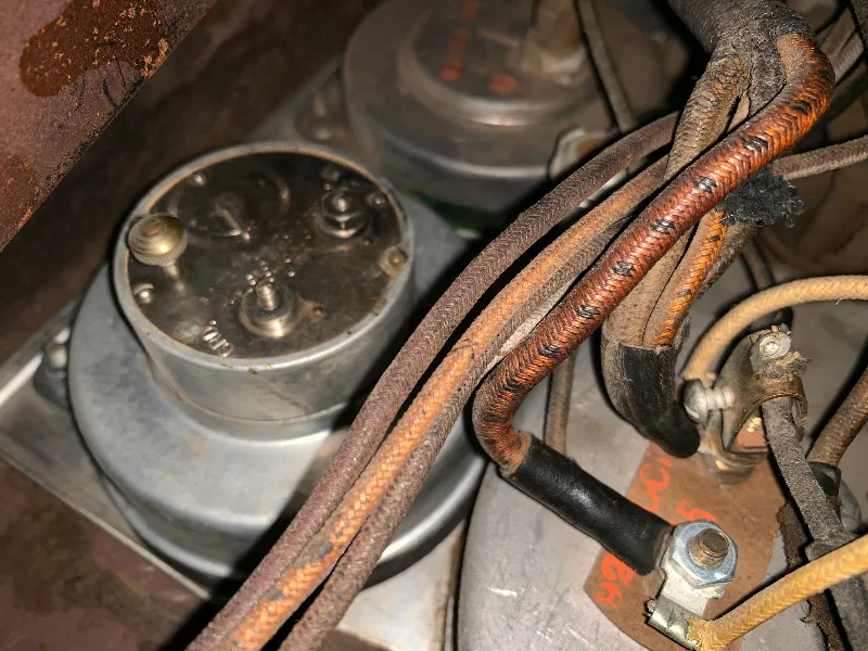
Hi Michael, your picture is interesting because my clock is upside down by comparison. Also the letters GRD are much more obvious than mine. In my case the letters GRD are closer to the perimeter and partly covered by the metal case.
Cords are one heck of a learning curve.
Happy New Year from Down Under ........................ we get there the day before you guys.
Here are some promised pictures of the clock and other dash gauges I restored. Enjoy.
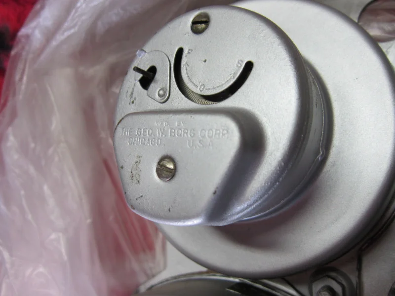
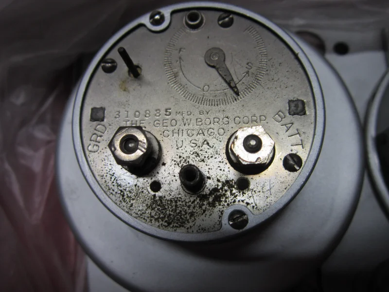
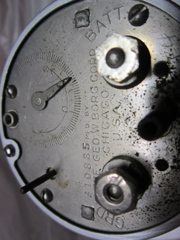
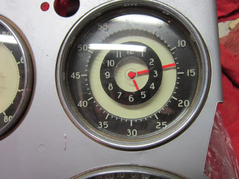
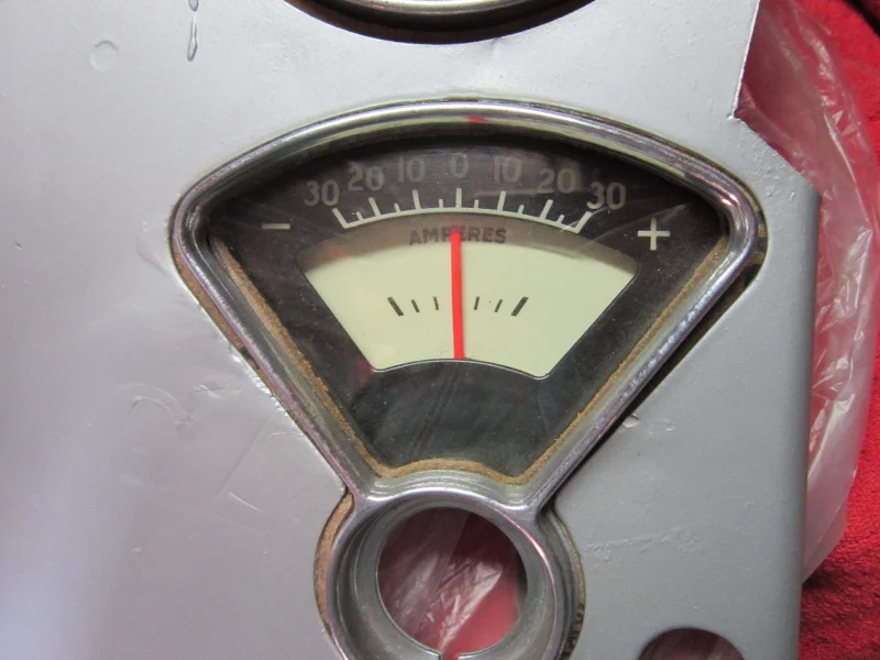
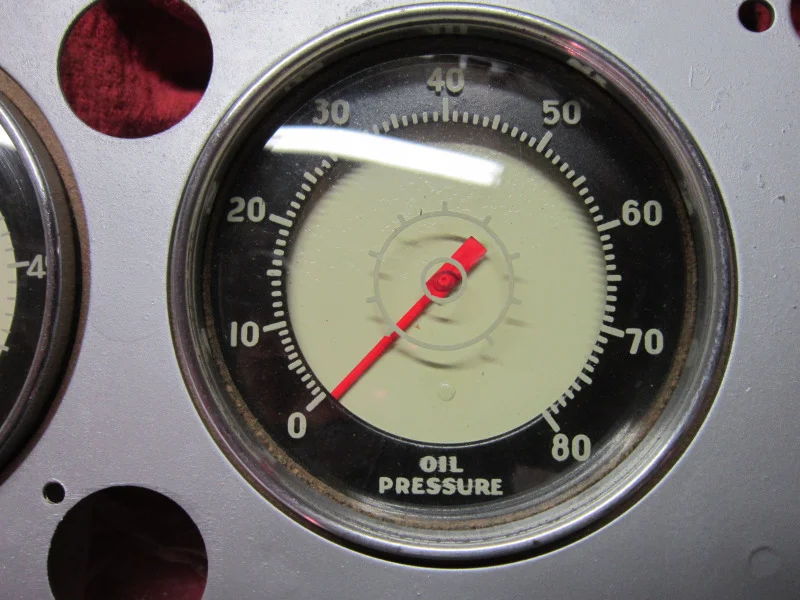
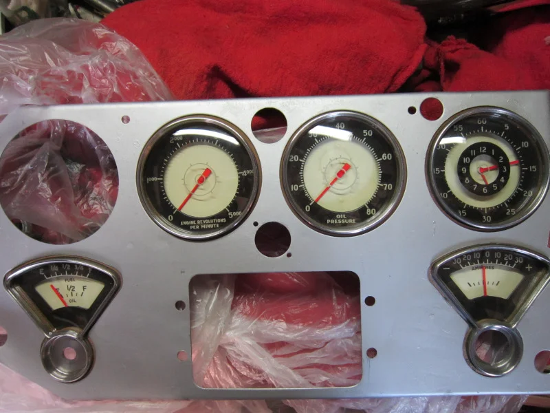
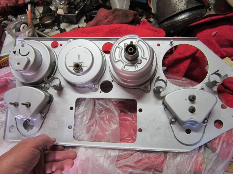
Hi Gary, your picture agree's with Michael's consequently at some point in time a previous owner removed the clock for some reason maybe repairs ? Later when it was reassembled the face was turned through 180 deg so when fitted the mechanism was upside down looking from behind. I guess it can stay that way until it is back on the road and I will eventually fix it.
Attached is a picture taken during dismantling, note the cardboard gaskets/cable protectors on the ammeter and fuel/oil gauges 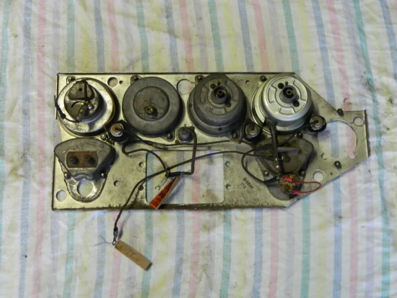
Hello Terry, I have those cardboard insulators on my work bench. I just have not put them back in place yet.Still working on the gauges. If I recall correctly you can remove the clock and re set it to be correct as it left the factory. I will remove mine and examine it to be sure of my advice. To take apart the gauges all you need to do is bend back the outside chrome cover. A pair of needle nose pliers works well.
 
 
Gary Parsons
Hi Terry, The clocks have a tendency to burn out the points. If I remember right you need to put a diode in the circuit to prevent this. There is an article in an old Newsletter that details this.
Jim
Jim could you please tell the forum what diode value to use or what older news letter this information might be in? Thanks from an interested way to save our clocks.
 
 
Gary Parsons
Easiest way to protect the clock's points is to make sure your battery is fully charged, OR,disconnect the battery when not in use.
The rewinding points will burn out if the battery gets too low
Easiest way to protect the clock's points is to make sure your battery is fully charged, OR,disconnect the battery when not in use.
The rewinding points will burn out if the battery gets too low
Thanks for this valuable information as to why the contacts burn out. My clock has not run because the wire harness has been removed for about 52 years. I should probably hot it up to test run it before I install my dash cluster. Thanks.
 
 
Gary Parsons
Clean the contacts and install a diode.
CORDiallyMike
I think I am missing something Mike. A diode only allows current to flow one way. If a diode is installed on a clock, how does this save it.
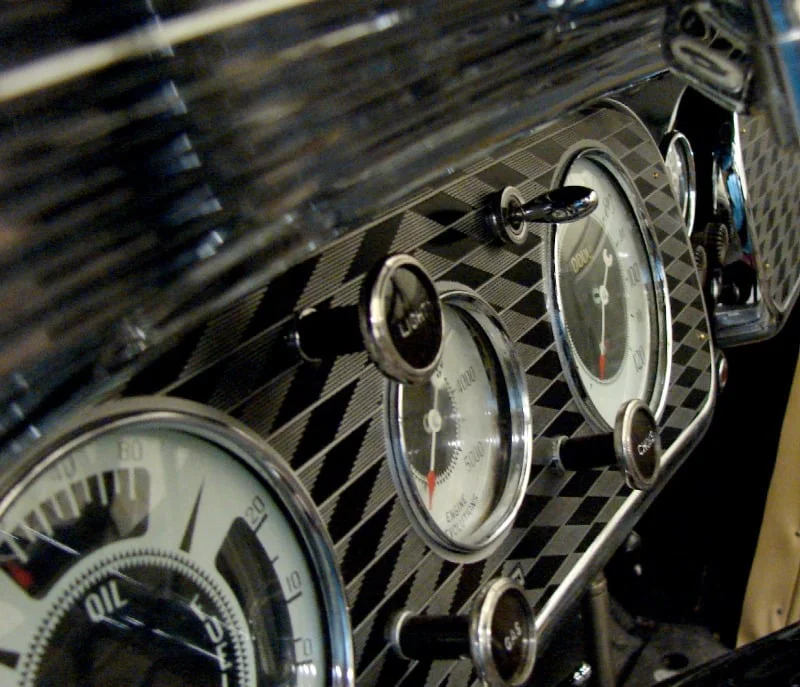
I use the 'banana' switch on the dash to power the clock. When I am going to shows, I apply power and it goes tick-tock. One can also power the clock off the IGN switch. No power to the points, no power to the clock.
it might help using a Z-Diode as we call it here. Installed in the "wrong way" it has a "break throug" voltage. Elektronic Generator Regulation works this way. With the right dimension of this diode and perhaps a pair of resistors and one transistor you can manage, that the clock is only operating, if the voltage is high enough to pull the magnet to the end. (the reason for burning the contacts is that the current flows till the battery is completely empty if the battery was to weak when attempting to pull.
My simple solution is to disconnet the battery when the car is parked for more then one day.
Curt, can you explain what is a banana switch ?
Powering the clock off the ignition switch makes sense.
Thanks,
Terry
Use a Diode 1N4148. Route the inductive current from the contact back to the other side of the inductor {allowing the inductor current to momentarily continue to flow when the contacts open} Connect the diode directly across the coil with the cathode to the plus side of coil. This is from a clock website.
CORDiallyMike
To join in the conversation, you must be a club member.
You’re welcome to read and like every post. Members can reply and start topics of their own.